Skip to content
- Spring Battery
- Dot-Bot Software Upgrade
- Model Railway Booster Fault Detection
- Dot-Bot Spray Can Upgrade
- Electronic Kalimba
- The Cleaning Bot
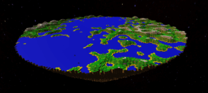
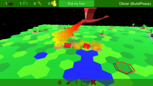
- 3D Terrain Generator
- Dot-Bot Gondola Update
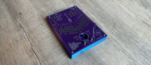
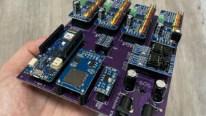
- Custom Development PCB
- Bahnhofs Steuerung 2000
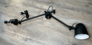
- Ikea Lamp Repair
- Crossword Auto Solver
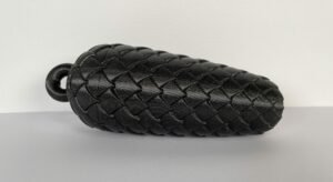
- 3D Printable Grandfather Clock Weight
- Marshmallow Mystery
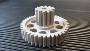
- Metal 3D Printed Replacement Gear
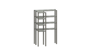
- Custom storage shelf
- 3D printed birthday gift
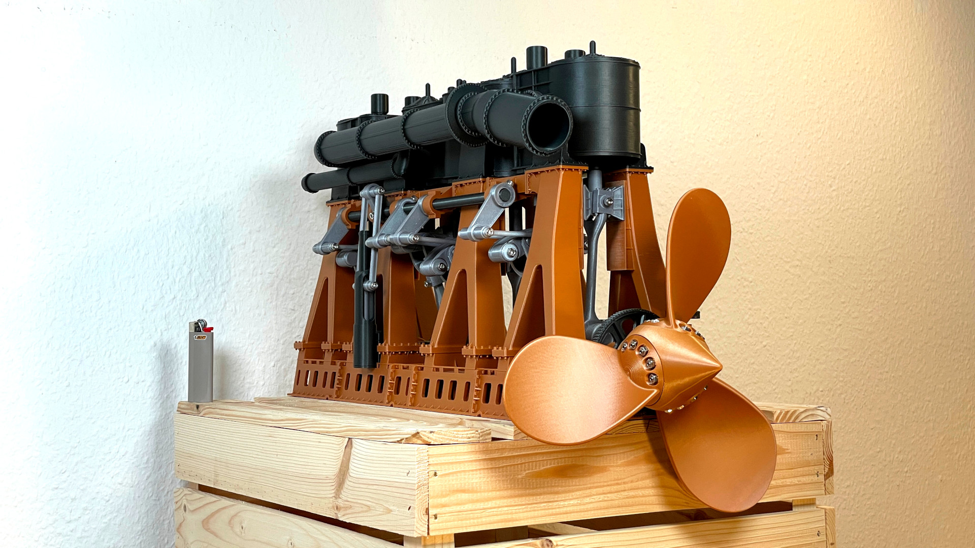
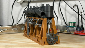
- Titanic’s Engine at 200%
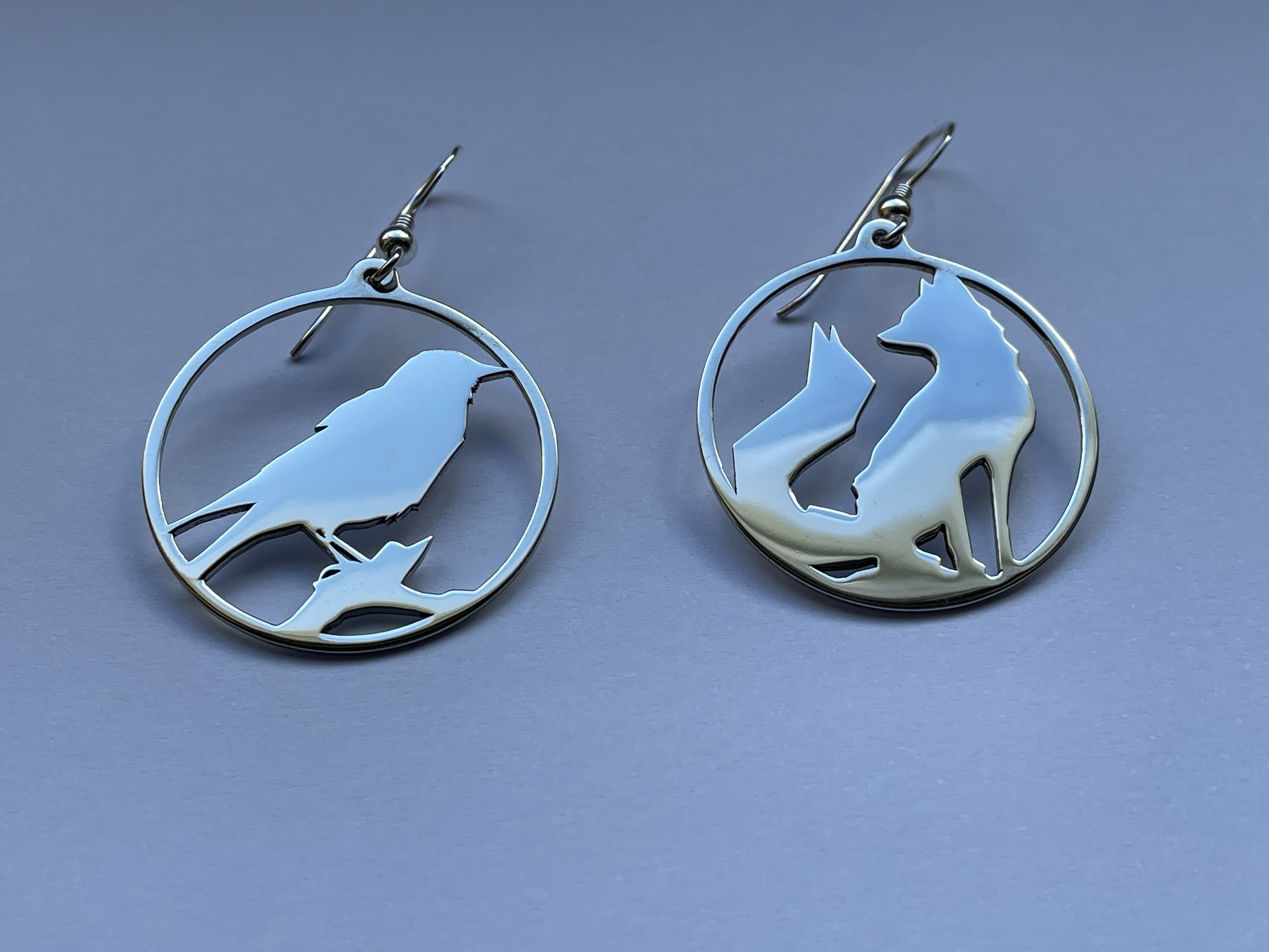
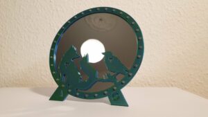
- 3D Printed Valentines Gift 2023
- Desk Fan Repair
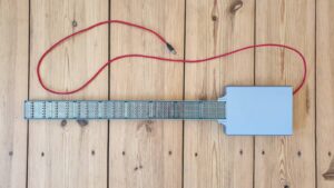
- Electronic Guitar
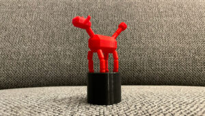
- 3D Printable Floppy Animal
- 3D Printable Airport Departures Sign
- DOT-BOT 2.0
- 3D Printable Titanic Engine 2.0
- Dot-Bot
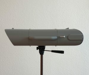
- 3D Printed VR Binoculars
- Kalimba Playing Robot
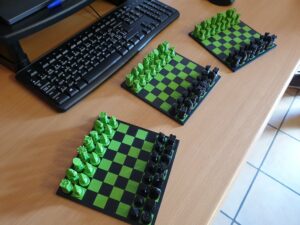
- 3D Printable Magnetic Chess
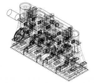
- Titanic’s steam engine
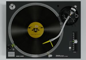
- Turntable Rendering
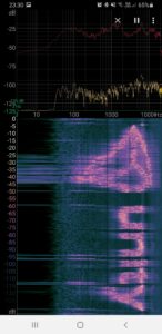
- Convert images to sound and back
- Atondes
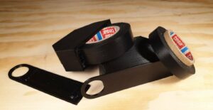
- Custom Tesa Roll Cutter
- Hex Tex Mex
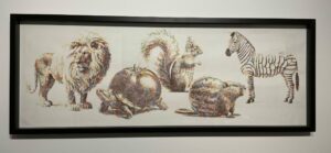
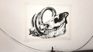
- 3D Art from Bugs
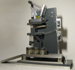
- M&M’s sorting machine