My dad usually has interesting challenges for me to solve. During my last christmas break at my parents place, my dad gave me my usual annual assignment. This time, he needed a way to intelligently power down parts of his model railway in case something goes wrong…
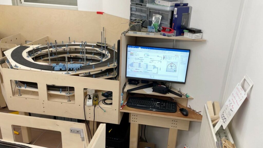
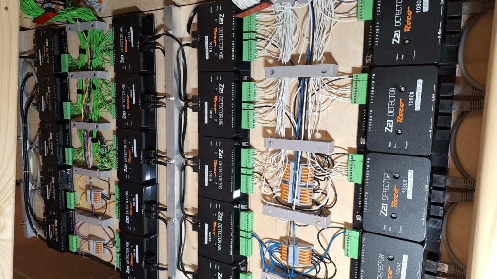
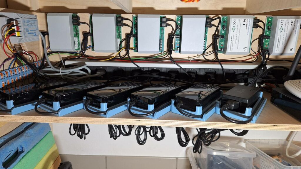
As a bit of context, he is building a sophisticated model railway where everything is controlled by software running on a computer. Trains can be sent autonomously throughout the entire system, where the computer changes rail switches and sets the correct signals for the trains journeys. This produces a stunning simulation of “life” when all of the trains are moving at the same time, in different directions and at different speeds. With the use of so called detectors, the system can also sense in real time where on the system trains are currently at. Several boosters are at work to power different parts of the tracks and one additional booster is used to power all of the motors for the switches.
One important thing to know is the fact that for electrical reasons, the two rails can never be connected to one another or will create a short circuit. But by setting switches incorrectly, or not setting a switch at all, a train can still push a switch open in one direction which then leads to an immediate short circuit. This usually only happens in manual control mode, since the controlling software sets the switches correctly before crossing them. If such an error occurs, you usually want to halt all other trains and resolve the issue first, before the normal flow resumes. In many cases, setting switches differently is enough to resolve the fault and be able to get all of the boosters back online.
For a more in depth explanation about the switches, my dad wrote a deep dive into their function and the resulting challenges which you can find here.
This is also where the challenge begins. First of all, boosters have no way of directly telling the controlling software if they are tripped or not. They can however propagate their error state to their shared hardware controller, which can then command all of the other boosters to power down and also forward the error to the controlling software. But in that case, since all boosters are offline, testing different switch configurations is impossible since the motors for the switches also have no power. Unfortunately, this is an all or nothing situation, where fine-grained control is not available out of the box.
Hence, the requirements my dad had were:
- If one booster goes offline, all train powering boosters should go offline
- If one booster that powers trains goes offline, the booster that powers the switches must remain online
- The track outputs from different boosters can not permanently be connected
- The solution should preferably not use microcontrollers or additional software
- The solution should use little current from the boosters
- The solution cannot interfere with the data protocol used by the system (DCC)
- The booster voltage can range between 12 V and 24 V
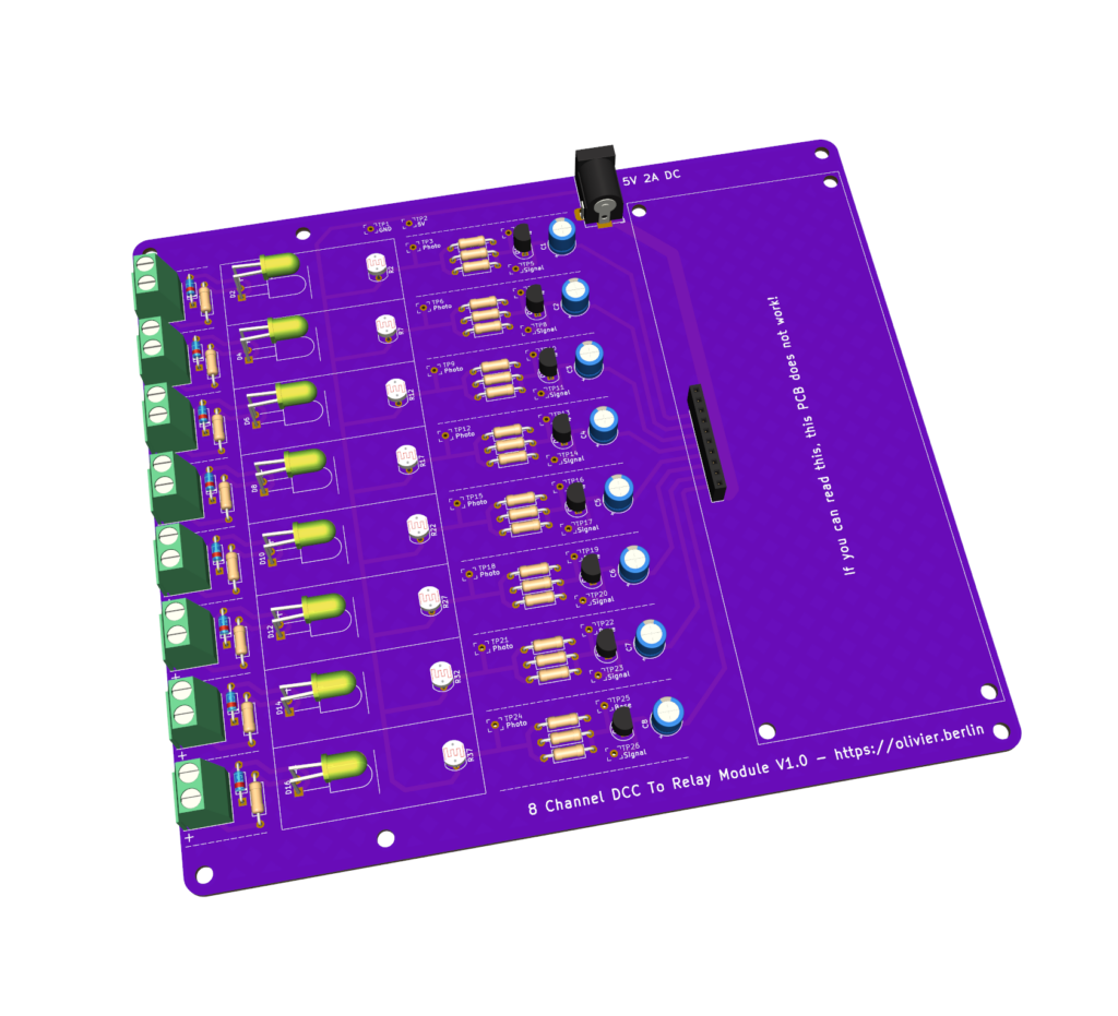
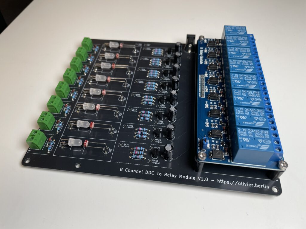
After thinking through many flawed approaches, the solution we finally came up with is quite elegant. To each booster’s output, we connect an LED with a large resistor and a switching diode, to produce a tiny light source. With a photoresistor, we then sense if the LED is on or off, basically constructing our own optocoupler. The resistance of this photoresistor is then used to switch a transistor on or off. The transistor again is used to switch an input of a relay card. The relay card switches one of its relays to toggle the state of an input on a detector. This basically simulates a virtual train appearing on a virtual track segment. This information can be forward along all other train positions to the pc. On the computer, the control software can use these specific input states of the detector to trigger custom actions in return. By setting the boosters via a jumper to not propagate their error on their own, we first prevent all boosters from going offline immediately. In the control software however, after sensing that one of our virtual trains has disappeard (and hence deducing a booster has tripped), we power down all remaining track boosters to prevent any collisions and further chaos, but without powering down the booster for the switches.
For all of this to work, only a handful of components are necessary.
Per booster to create a signal we need
- One LED
- One switching diode
- One 10k resistor
Then on the other detecting side, we need per channel
- One photoresistor
- One 10k and two 2k2 resistors
- One 2N2222 transistor
- One capacitor to smooth out the signal
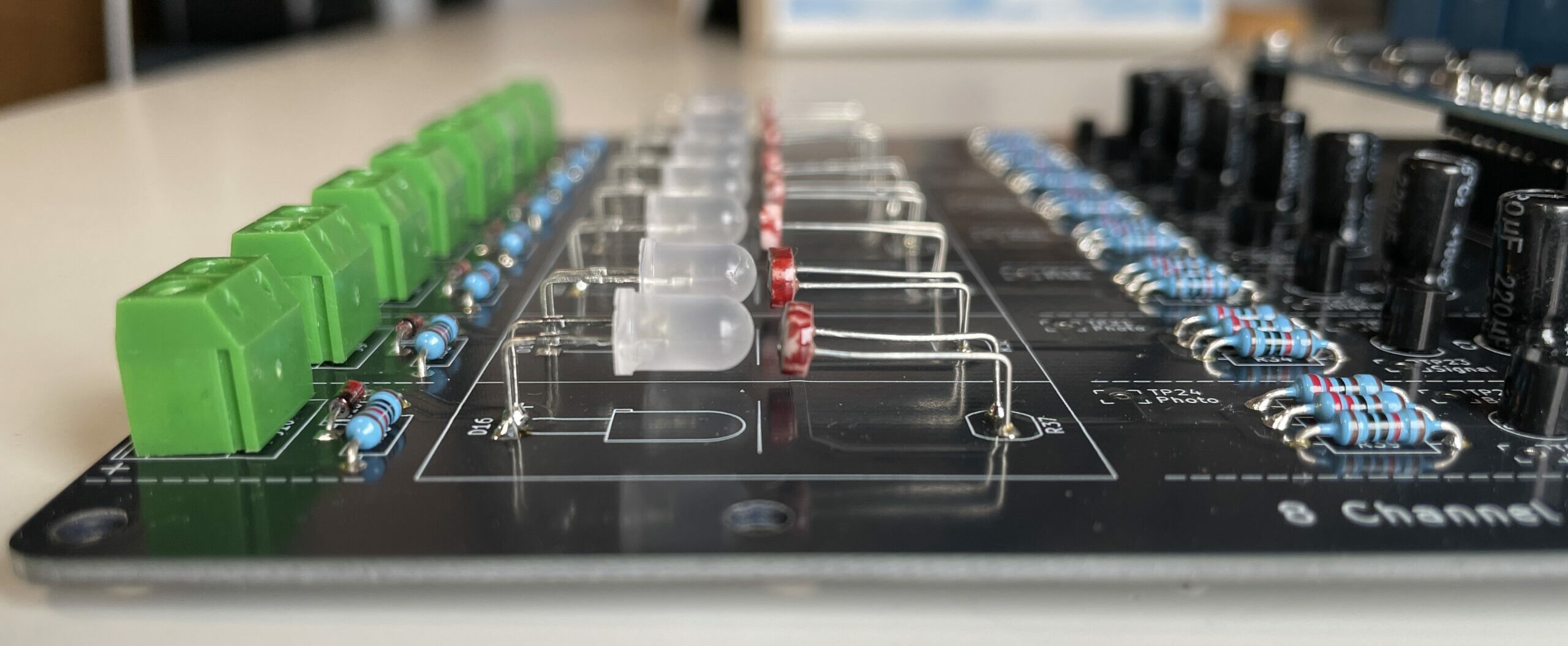
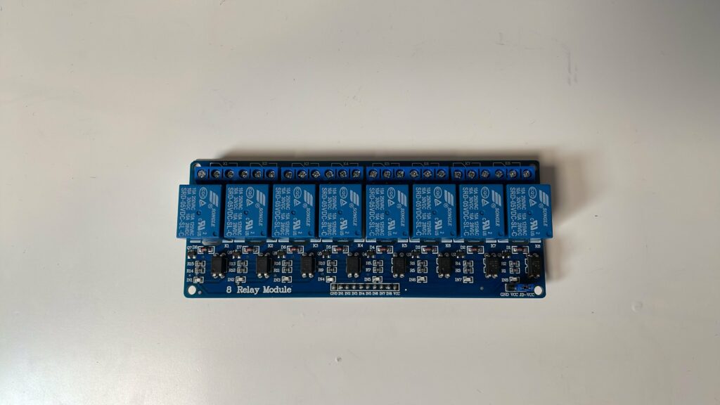
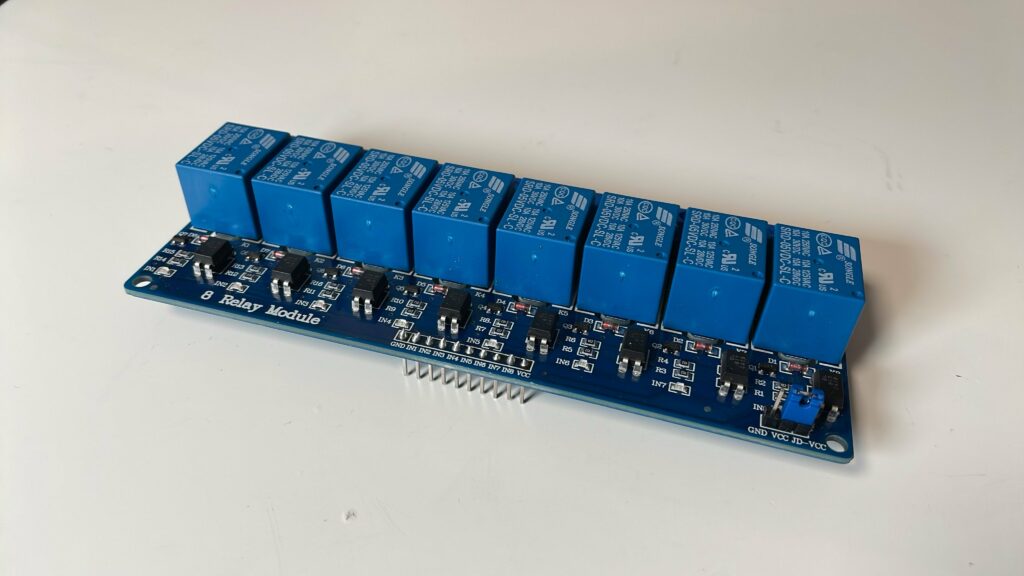
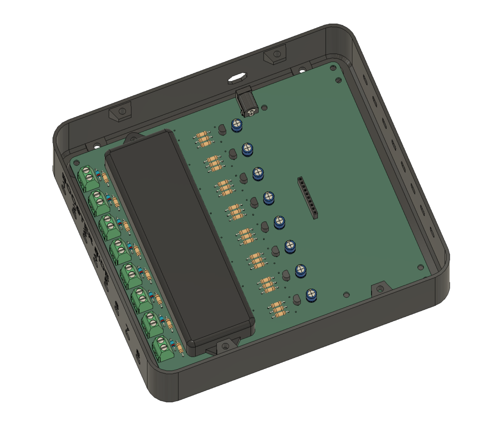
Also, to interface with the detector, we need a standard 8 channel relay card. The only modification to this piece is the pin header. It has to be desoldered, and then resoldered from the back such that the relay card can be used as a plug in component on the PCB.
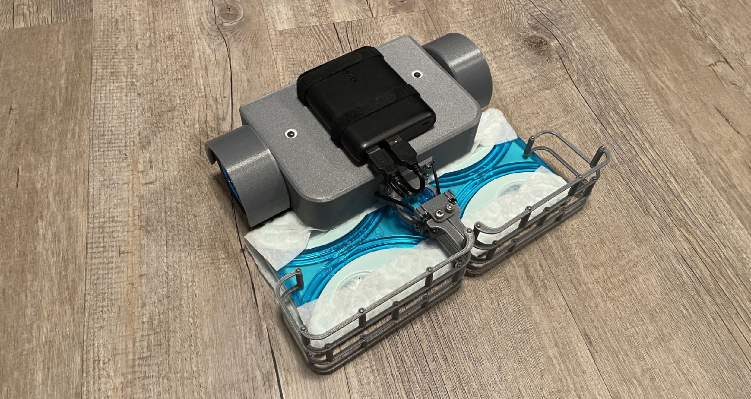
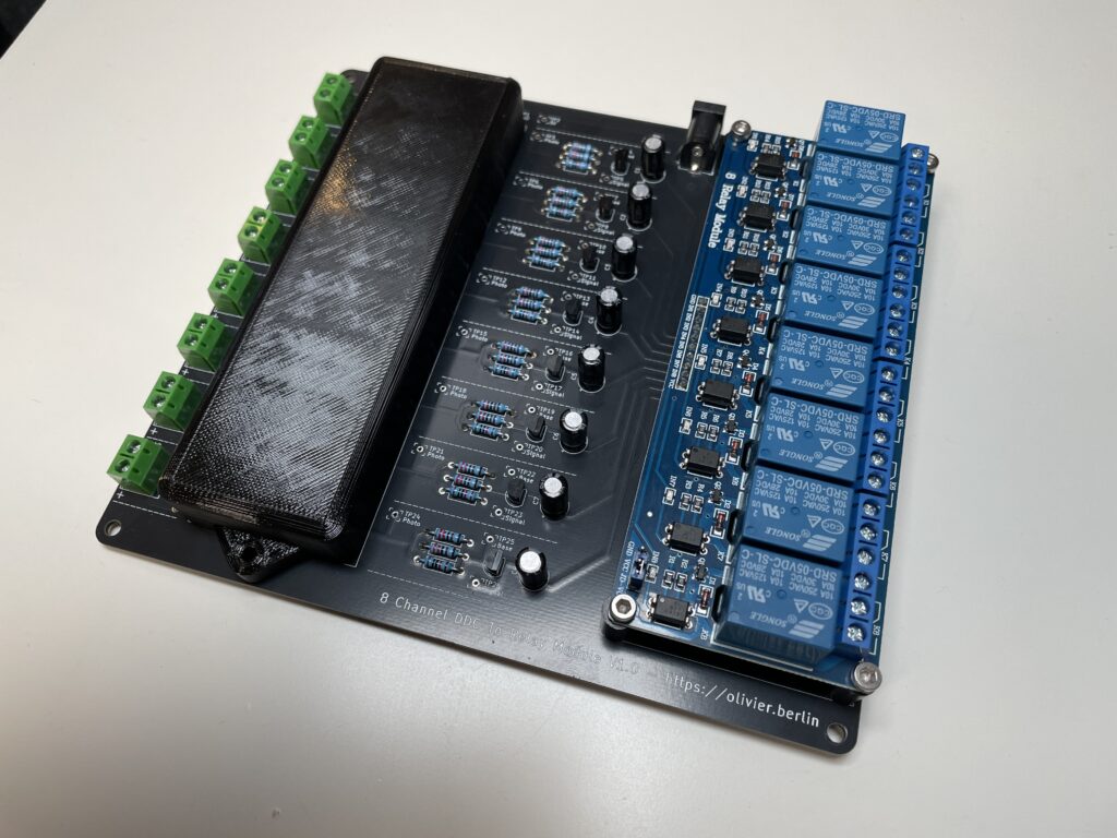
To make everything nice and tidy, I designed a PCB around this setup that adds a few connectors and has mounting holes for a 3D printed isolator for the optocouplers, although my test showed that they already work fine without optically isolating them from each other.
Here a small cost overview for this project:
- 25€ for the PCBs (min quantity 5x)
- 10€ for the relay card
- 5€ for the 5V power supply
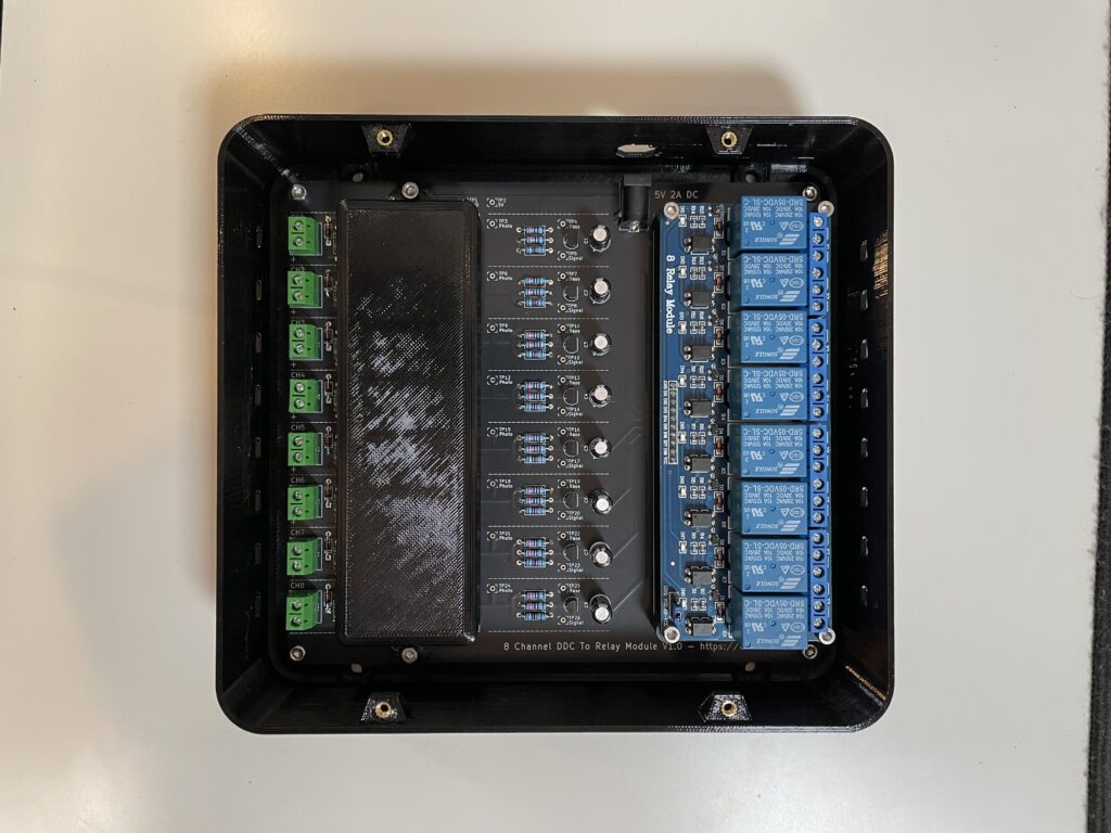
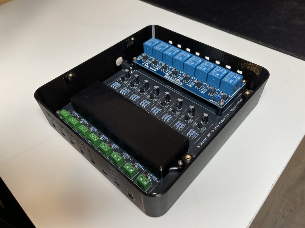
- 2€ for the 3D printed case
- 1€ for the additional components
With the PCB having its own power supply for the relays and the transistors, and all signals transferred optically or via relays, every channel is galvanically isolated on the input and on the output side. This minimizes potential sources for problems and makes this solution not only cheap but also reliable for years to come.

If you wish to have a specific electronics problem solved, please write me an email with your issue using this email address.