After 4 Years, the time had finally come, the Dot-Bot project, that actually started its journey with the name Spraybot was allowed to do what it was designed to do, and what its logo was still showing to this day, painting with a can of spray paint!
But how did we finally get here, after this idea was slowly buried underer loads of other projects? A professional artist from Germany Jascha Müller (https://jaschamueller.art/) called me, and asked me about my drawing robot project, knowing I had done some large scale (pen) paintings with my robot. He explained that he also worked on a drawing machine in the past, that was able to use a spraycan to plot images onto a wall. However, his gantry approach did not scale up very well and he was intrigued by my polargraph, which was already fitted with 10 meters of GT2 belts on each side.
He then asked me if I was interested in revisiting my drawing robot and to make it ready to draw with spray cans. I was more than happy to accept his offer and he then got in touch with old friends in Berlin that had the perfect spot for testing for us.
Although the robot was working fine in my clean and tidy room scale setup using pens, I knew I had to redesign several parts to make everything work reliably in a potentially much larger and less friendly space. Also, due to limited time constraints, I had to make sure that on site assembly would be minimal.
Most notably, the changes that were done for the first day of spray action were:
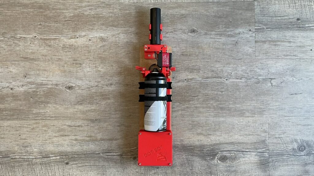
Developing a Spray Gondola
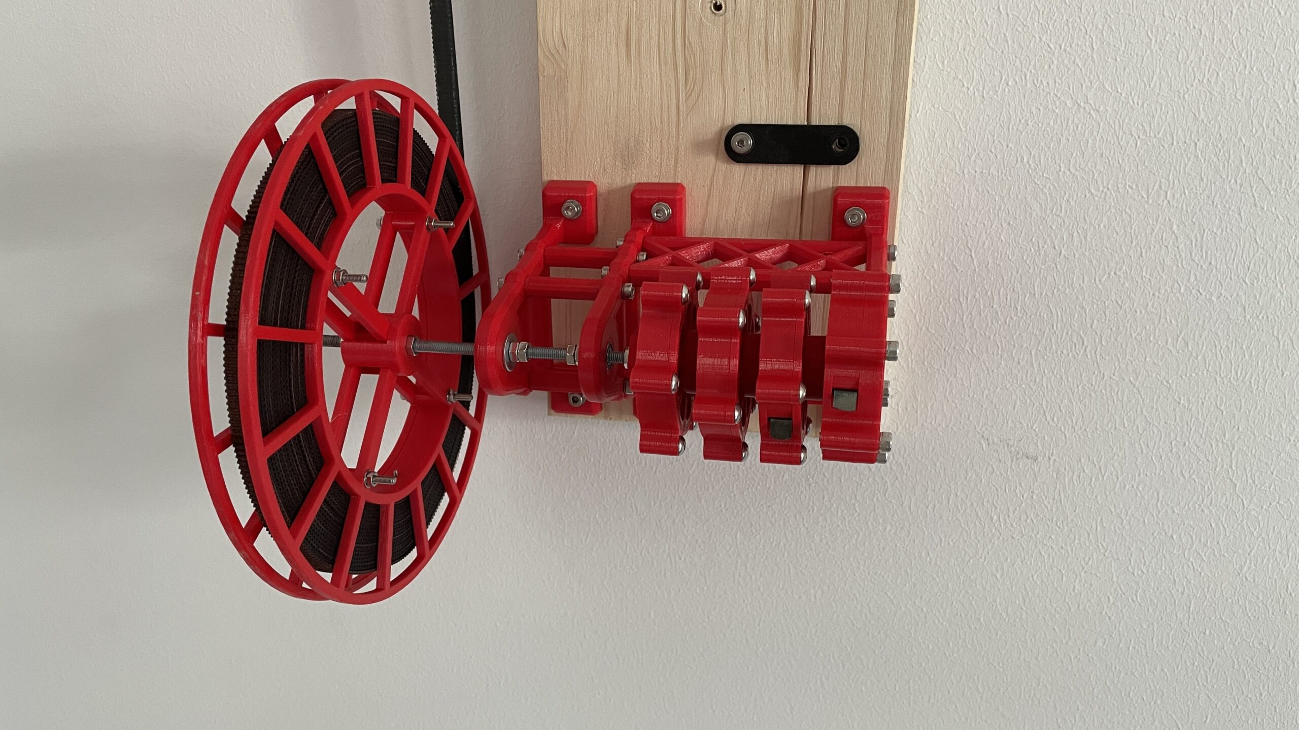
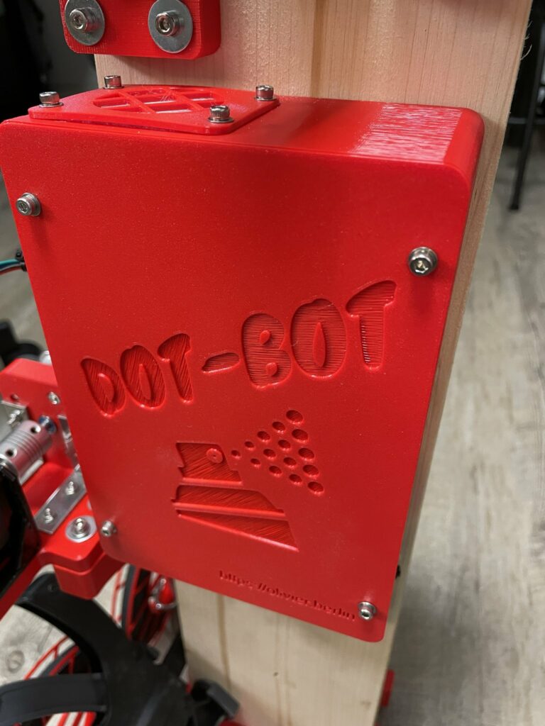
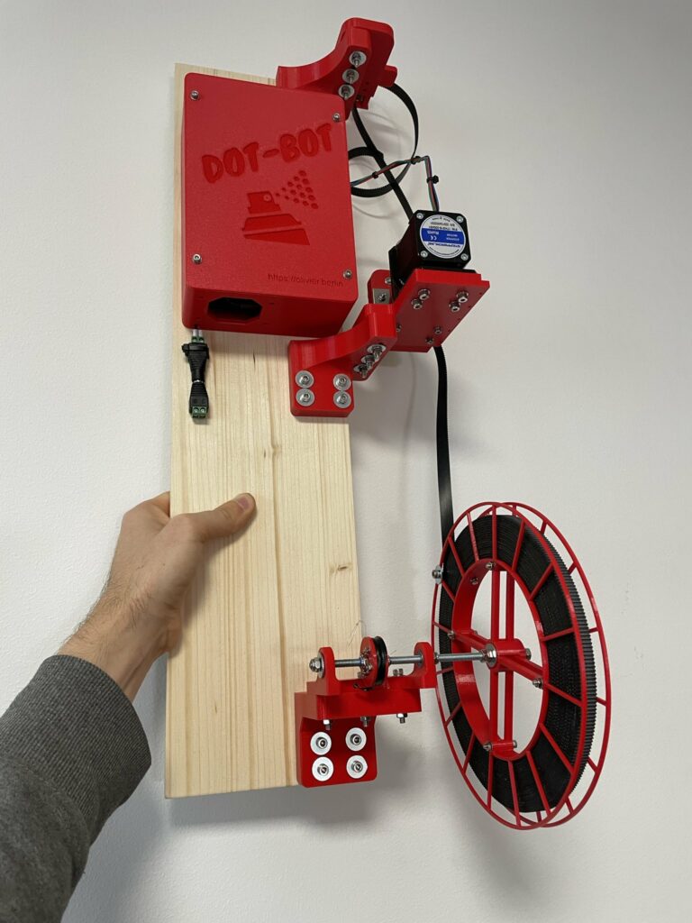
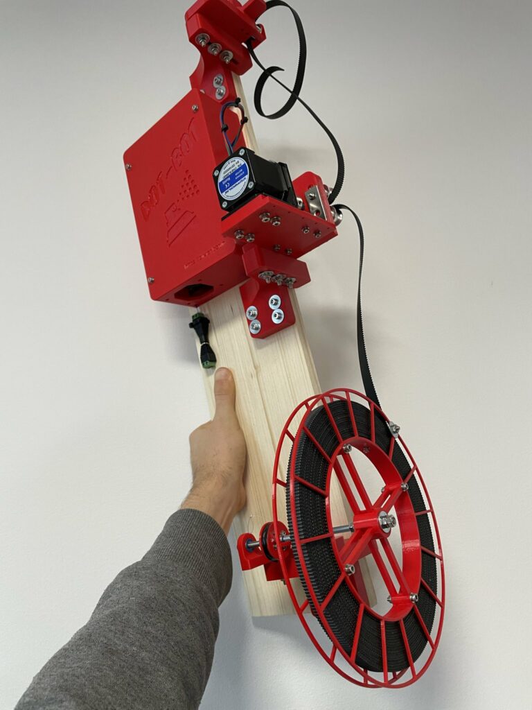
Until very recently, every gondola design cycle revolved about the ability to push a pen against the wall. For this iteration however, spraycans were the name of the game. Since I was already quite happy with the last gondola design, I reused several parts like the battery holder and the electronics compartment, but redesigned the mount for the spraycans and mounted everything on a wooden board, which is more economical than to 3D print a large slab of plastic. A noticeable upgrade is that I preserved the USB cables data lines, which means I can now reprogram this new gondola by attaching a USB extension to the battery compartment and my PC without the need of disassembling the electronics every time (Yes, I learn from my mistakes).
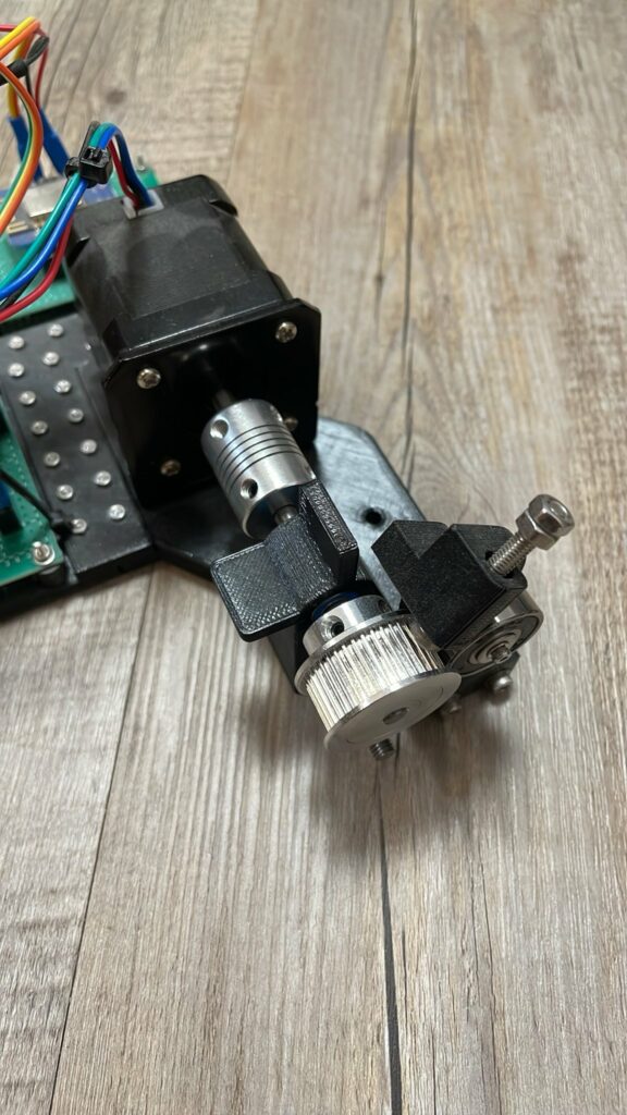
Splitting up the Motor and the Final Pulley
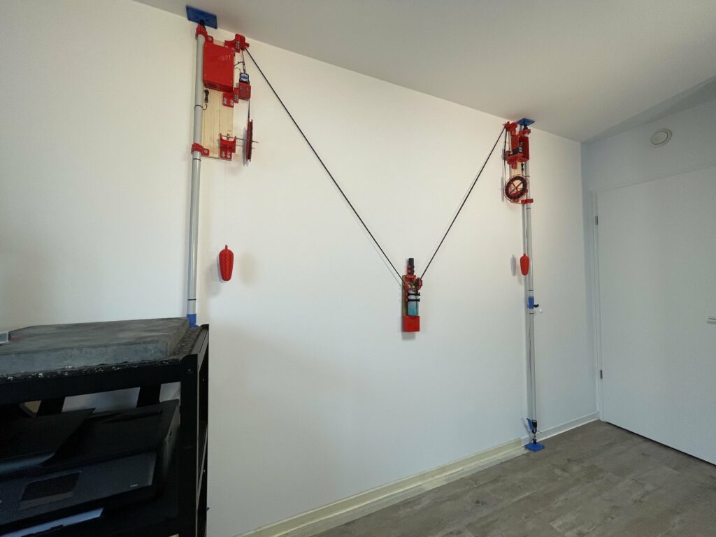
On my wall setup, the “stations” contained the motor and were at the same time also the final pulley that the belts were finally redirected from. This meant, making a larger canvas available, would require the entire station with electronics and motor to be mounted at the maximum height. With the new approach, only the free rolling final pulley needs to be mounted at the max height. The motor can now be inline in the belt in the downwards path. This uses more belt, but allows for an easier installation of the redirection pulley e.g. on a wooden post, without the need to worry about power cables, wifi strength, weight and space constraints etc.
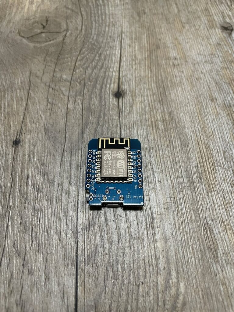
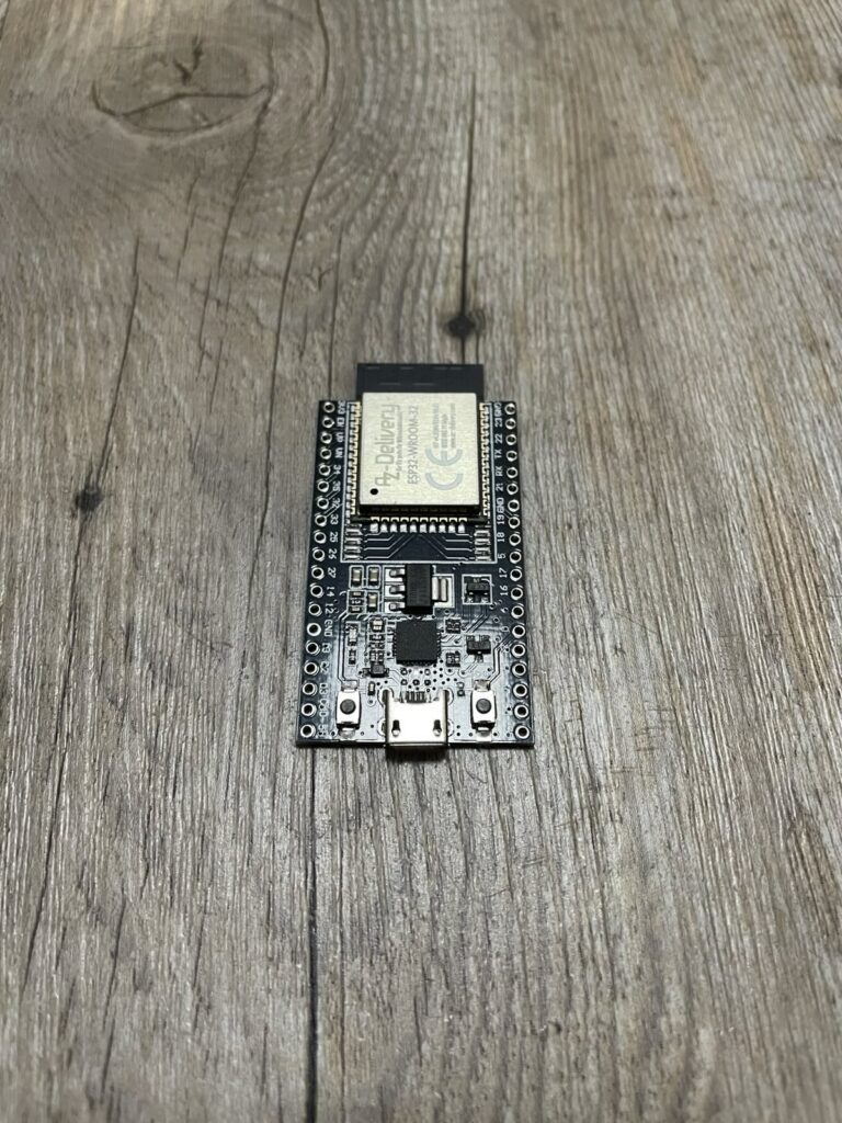
The upgrade from ESP8266 to ESP32
The old setup used two ESP8266 for each motor station. Each pair shared their work with one managing wifi communication, reporting and buffering and the other one only driving the motor using the AccelStepper library. This worked fine when the project was entirely private, but you cannot use AccelStepper in commercial projects for free, which this project inadvertently has become (since the artist paid me to develop all the required modifications) and therefore a switch to a different library was necessary.
Also since I always wanted to open source all of this project at some point, I really wanted to replace AccelStepper with a library that had a more open license. AccelStepper uses GPL V2 which would have meant that I would have needed to release all of the code under this license as well. Lots of projects stay away from GPL code for this exact reason and to increase the chance someone can reuse this code, I really wanted to use “MIT” licensed libraries only.
Luckily, I found FastAccelStepper, a different library that can be used as a drop in replacement with the desired open source license. The downside of FastAccelStepper in this project was that it does not run on an ESP8266. Since the library is perfect, I decided to upgrade my station microcontrollers!
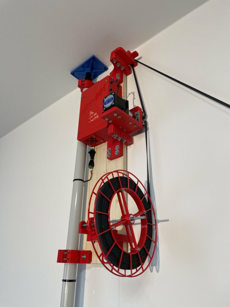
Getting rid of the Birds Nest
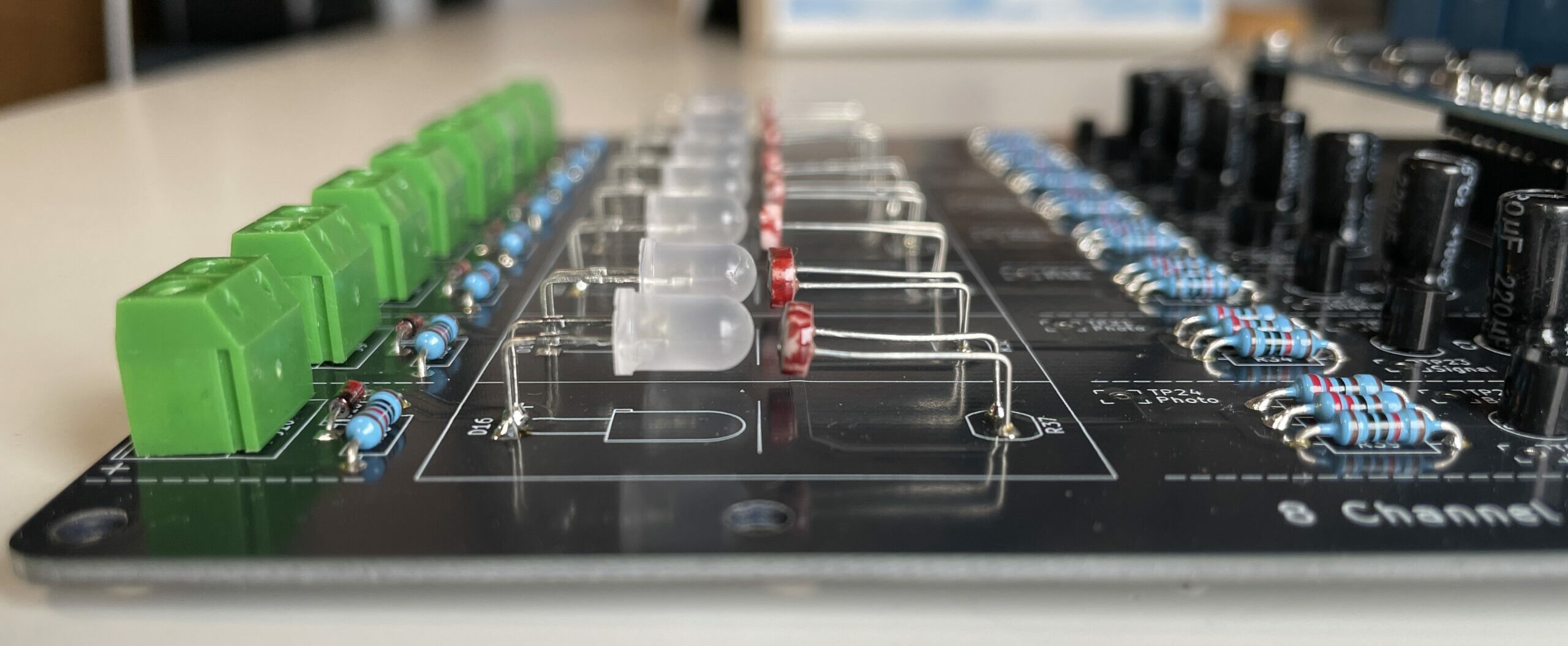
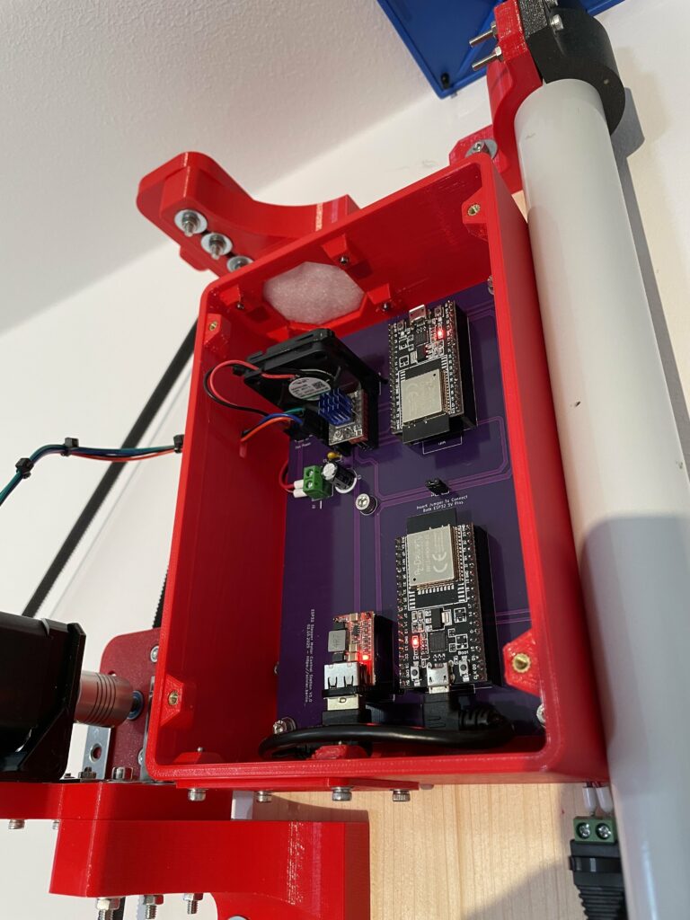
One major constraint is the sturdiness of the entire construction and therefore also ease of use and transportation. My clean lab setting is very gentle, and therefore the electronics worked fine even when all the wired connections were made by plugging jumper cables. However, for any serious use in the field, or already during transportation, jumper cables are a potential source of trouble. Therefore, and not because I acquired the skill of PCB designing and want to use it on every project now, I opted to design a simple but clean PCB that was capable of housing two microcontrollers, a motor driver and a voltage regulator. After only 10 days (thanks to priority shipping), I held the manufactured PCBs in my hands and they worked beautifully after assembly and powering them on. Now, even the biggest vibrations are unable to mess with any connection and will therefore facilitate transport, setup and debugging of the robot by a lot.
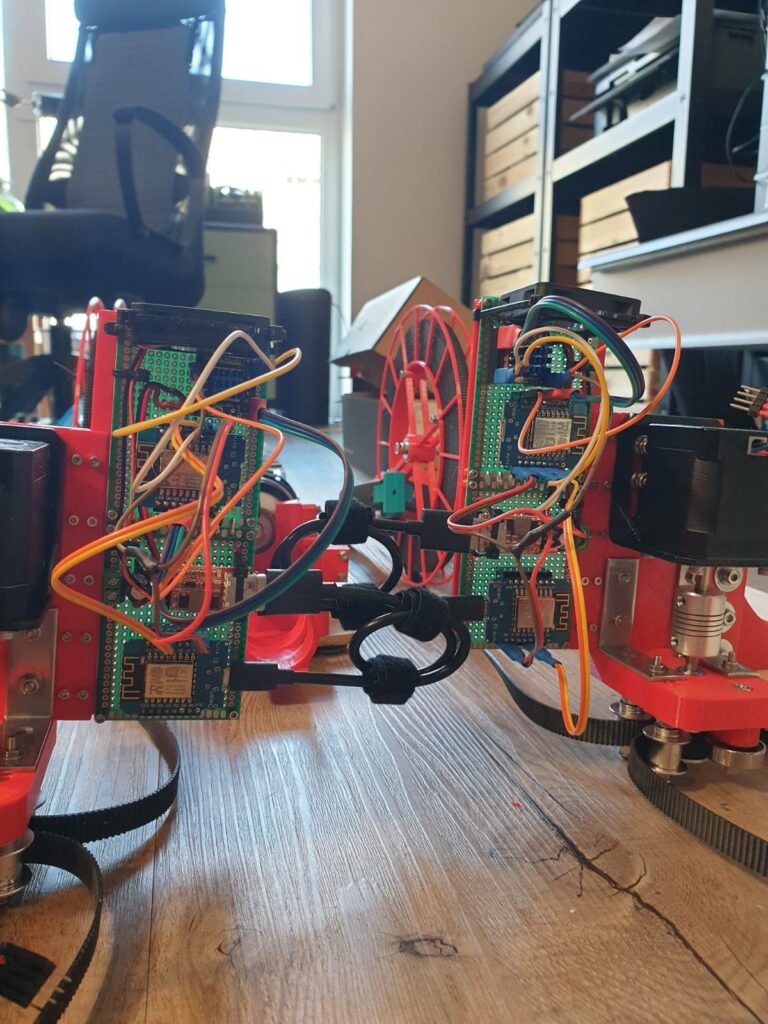
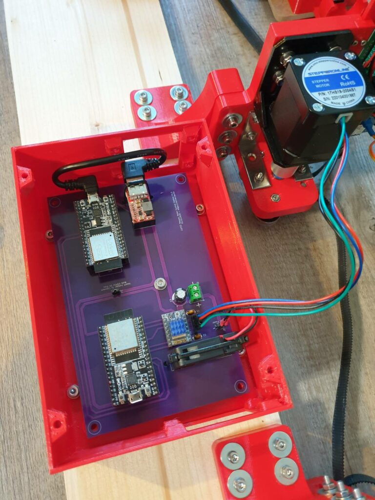
Protecting the Electronics from the Elements
Since we want to do outdoor testing sometime in the future, I did not want to have the electronics exposed to the elements. I therefore opted to design a neat case that can house the PCB, and has only cutouts for ventilation and cables. This should keep light rain, dust and occasional bird droppings out and further increase reliability.
Preparations
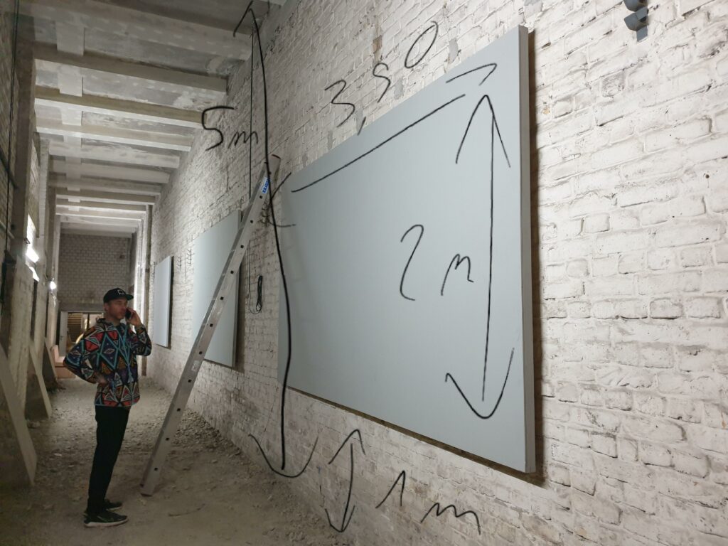
The second time the artist and I met in person, we met at the location we could use for our tests. A rough wall in a basement, nothing fancy but 5 meters high and perfect for our use case.
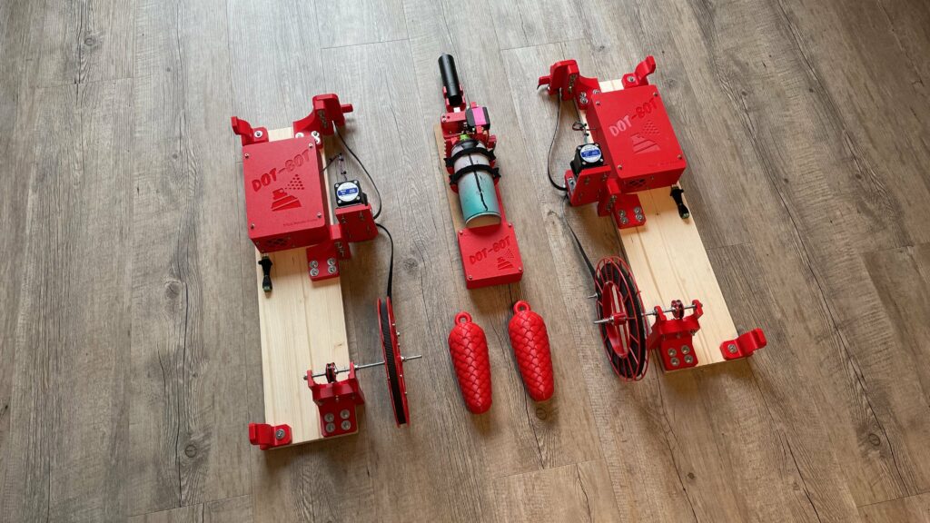
Since the wall was bumpy, and I knew we would only have limited time during our first test run, I decided to premount all of the station components onto wooden boards such that we could attach each station to the walls by only using two more screws.
I then 3D printed standoffs, to test these completed assemblies in my lab environment to make sure we would not have to deal with tiny screws or belt alignment issues at the location.
First Test Run
The day before the big day, I packed up the entire hardware and prepared as much as I could.
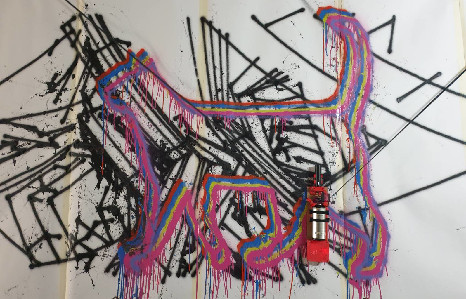
After only a few weeks after the first contact, we met up for the third time. This time, we had a clear goal in mind. We really wanted to see if this robot can actually spray!
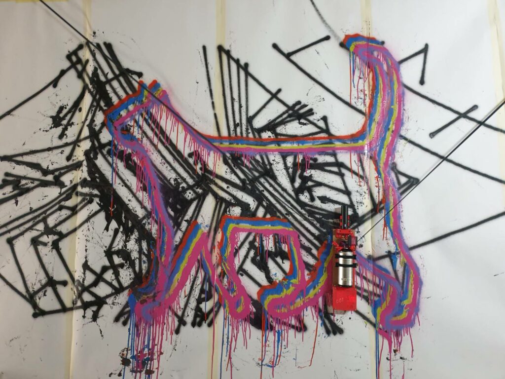
First, we got to the hardware store and bought protection to not spray directly onto the walls, but onto some white wallpaper. We then headed to the location and set everything up which went surprisingly smoothly.
When we put a can into the gondola, we were both full of anticipation of what to expect. Would the servo be strong enough to actuate the cap, would the speed of the motors be sufficient to create a nice line, would the wifi connection hold up and so on.
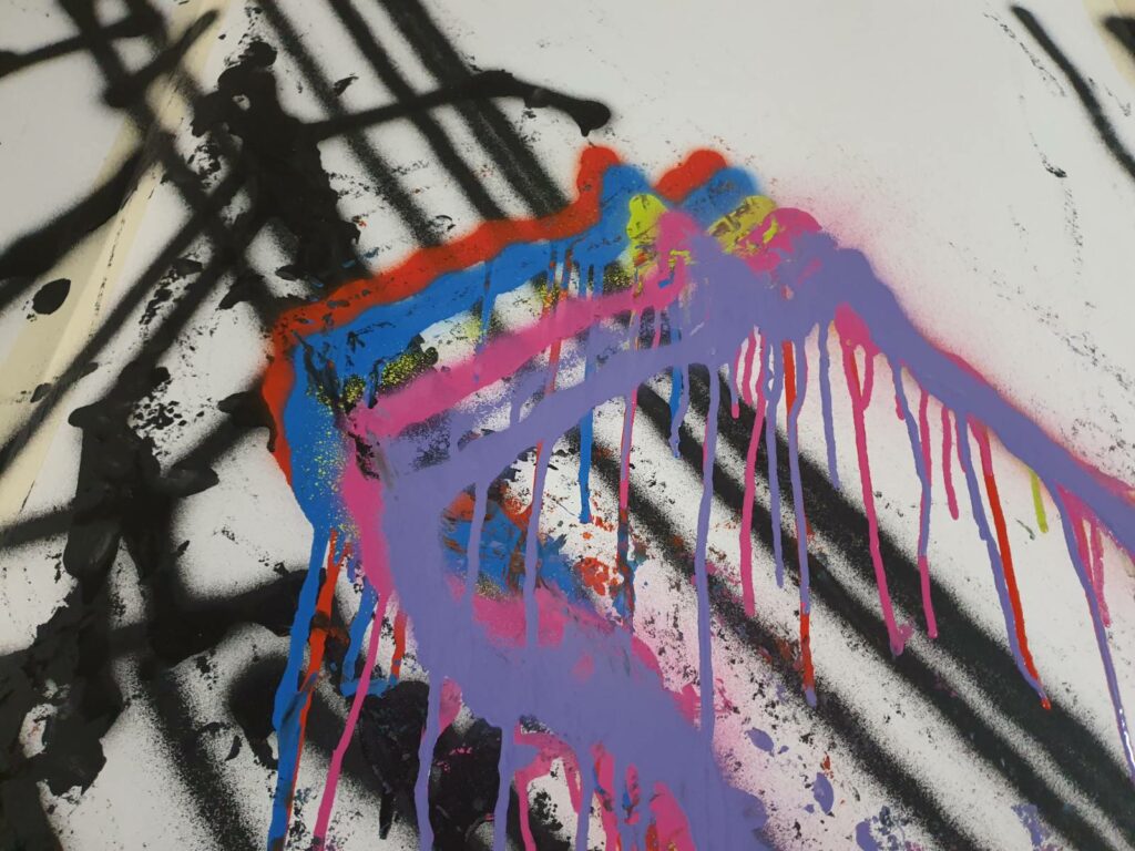
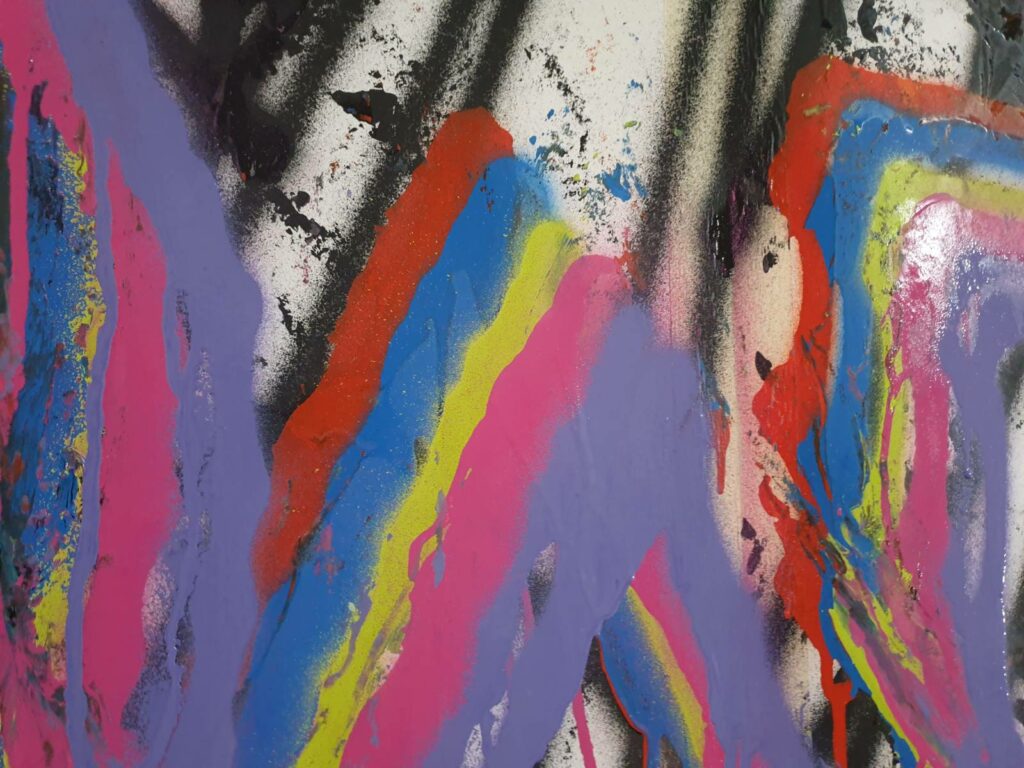
Surprisingly the test was a blast. After I changed so many variables in this project, without the ability to test everything in full in my lab, I did not expect the Dot-Bot to perform as well as it did. Sure the painting we produce does not look like much, but given that our goal was to draw a single line, we managed to exceed both of our expectations by a ton.
What’s Next?
When one thinks about the differences between pens and spraycans, one big challenge becomes immediately obvious. Spraycans will apply a lot of paint in one spot when not being moved sufficiently. Pens suffer from the same problem, but much less severe. Some pens like ballpoint pens don’t even suffer from this at all. This means spray cans should really be used with a constant speed. During the next weeks, the software will get an additional feature that allows the gondola to move over different waypoints, without completely stopping at each coordinate and accelerating again. This will mean that the dripping will be much less, and images with more coordinates can easily be used without wasting a ton of time for accelerating and decelerating.
Another planned improvement is a refined spray mechanism. We found out that pressing a can with a servo is too unprecise. One step is off, the next step is “too much paint”! A reduction mechanism will therefore be added to give finer control about the amount of paint that will be applied at any given point.
Also, some optimized artwork will be prepared such that the next canvases will become true masterpieces for sure!
If you have an idea for a custom robot or want to provide us with the next wall to test on, please contact me via email!