This is not just a small update. Almost every part of the project got redesigned and many technologies changed. This is such a major leap forward that for me it feels like a new project altogether.
After the update, the combined error was reduced from 4-5 cm / 100000 coordinates to literally zero. The speed of which the bot is able to plot at got upped from 1 dot/s to almost 4 dot/s. Last, the precision at which a coordinate can get reached on a 3m x 3m test canvas got down from ~1 cm to 0.1 mm
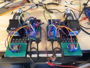
Here is a list of the biggest changes and what they mean to the project in no particular order
Encoded DC motors -> Stepper motors
The first version of the project used encoded geared DC motors. They had the drawback that the microcontroller needed to precisely count all the rising edges of the motor encoders. Any missed edges would result in an accumulating error. During communication and other blocking tasks, those interrupts would get ignored quite a few times which lead to an offset of a few centimeters after only 100000 reached coordinates.
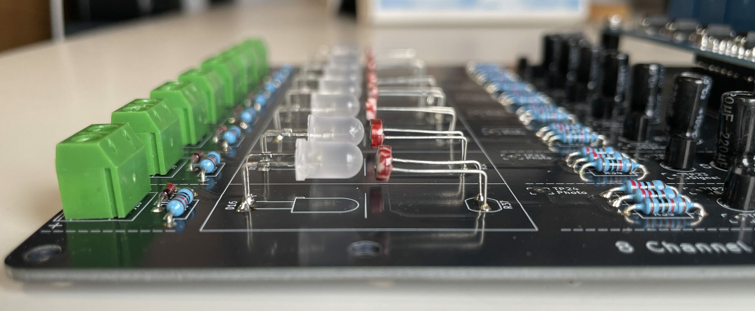
The new stepper motors however are indirectly controlled by the microcontroller via a TMC2209 stepper motor driver. This driver can calculate microsteps which leads to super smooth movements and almost no audible noise. Due to the nature of sending complete steps to the motor drive, no steps can ever get lost in the process. Also, using a library that comes with ramps, the bot can now move much faster from one set of coordinates to another, without ever under or overshooting.
Different types of wire -> GT2 belts
In the beginning, we wanted to make the bot as affordable as possible, and hence decided to go with pulleys with simple rope or wire. We tried different materials, each with its own challenges and were never quite happy with the result. E.g. nylon had a lot of stretch to it. In regimes of higher tension, the rope would stretch in a way that was not easily compensable by adding or subtracting a simple factor. Thin steel wire on the other hand always tried to clump up on the spool, thus changing the diameter of the spool in unpredictable ways which resulted in undesired patterns over the images.
The Dot Bot 2.0 uses 10mm wide GT2 belts. These belts have little to no stretch to them, and in combination with the geared and smooth pulleys, they have no slip whatsoever.
Spool of wire -> Gravity tensioned secondary belt holder
The bot was always planned to have a drawing area of approximately 10 x 10 meters. To achieve this, a lot of additional length needed to be stored somewhere. The first version of the bot did this directly on the axis that was connected to the motor. In an ideal world, every N revolutions of the motor you would assume a slightly changed diameter and everything should remain precise. But the wire and nylon always tried to spool on top of the highest point on the spool making this assumption not work at all
The new system however stores the additional length in a secondary system. This system is gravity tensioned by a weight which allows for a smooth addition and release of the belt. With this system, the belt can now be almost endless with no further modifications. Right now, each side holds 10 meters of said belt.
1 microcontroller per side -> 2 microcontrollers per side
The first Dot Bot used one microcontroller per side, to do all of the wireless communication with the server as well as commanding the motor and counting the interrupts. We found out that using Wifi on a microcontroller involves a lot of blocked time, where the processor cannot react to interrupts or produce signals to command the motor.
Therefore, we switched to a two microcontroller system. One for coms, and the other one to control the motor. Both controllers are connected via a serial connection and with a very basic communication protocol, the secondary microcontroller only gets an absolute amount of steps to go and reports back once its duty is done. This ensures that the motor can run as quickly and as smoothly as possible.
12V -> 24V
Initially, we planned to have the stations running off 12V DC. This seemed to be a good compromise between availability of batteries and losses. But with the new motors that can draw up to 3A, 12 V was simply too little. For testing, the stations are connected to a bench power supply through 30m of copper wire and the measured voltage drop was approximately 10%. Now with 24V, less power is wasted over the lines and the stations get a much more stable input voltage.
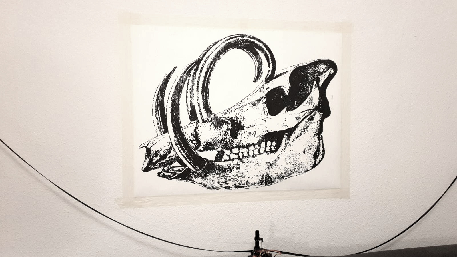
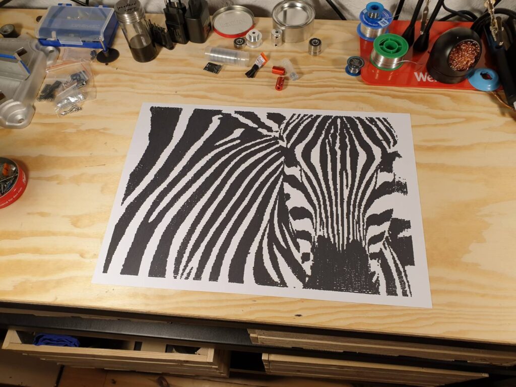
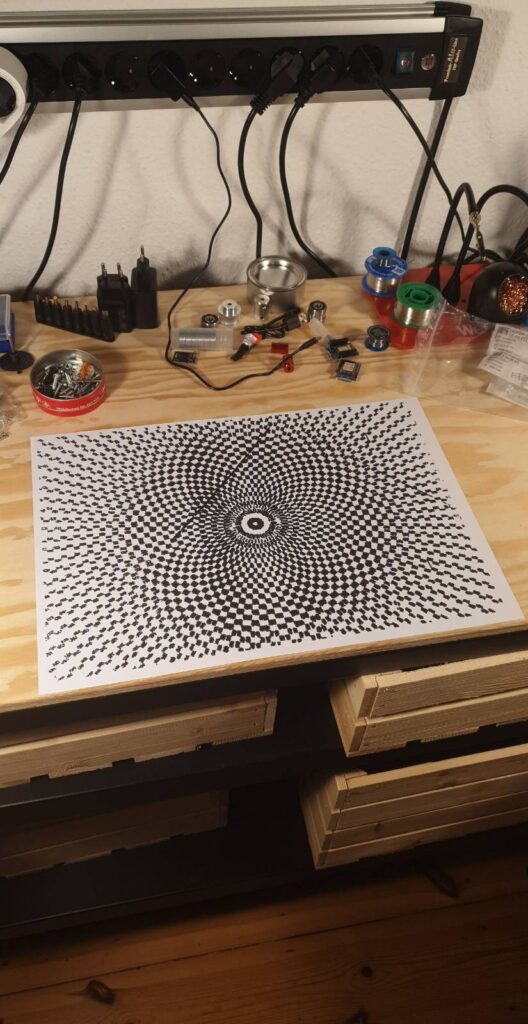
Smaller images (A3) that were plotted while testing
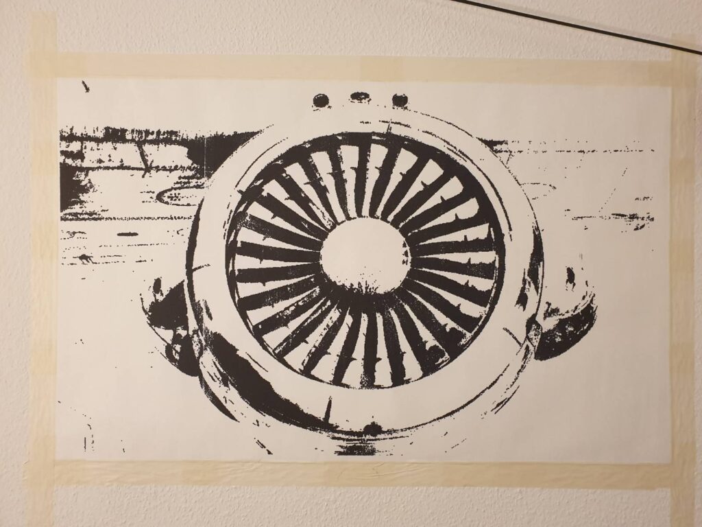
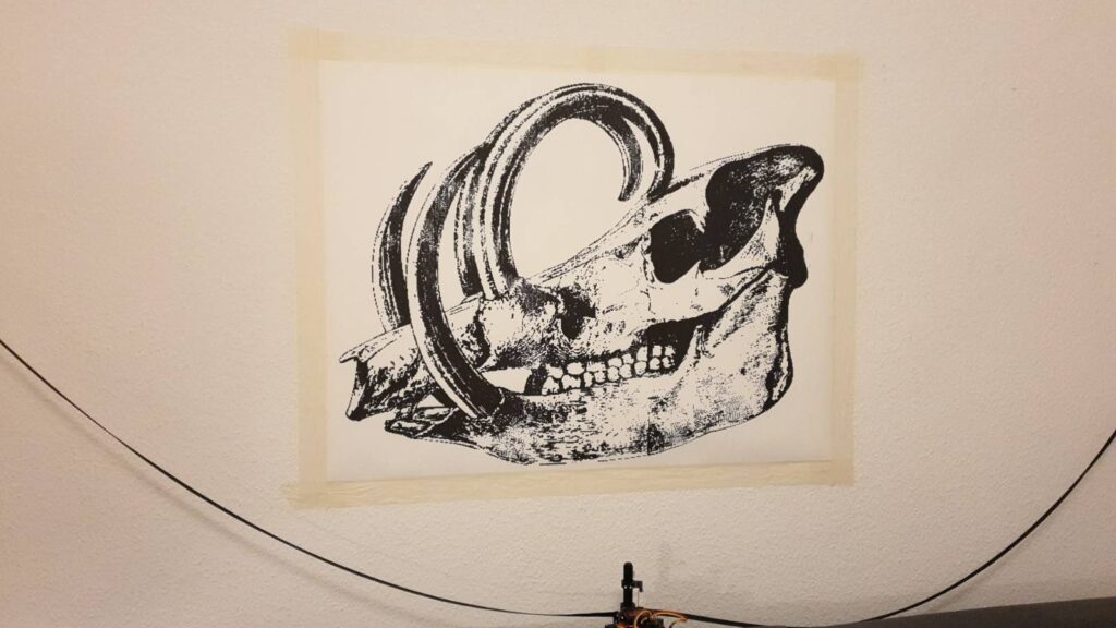
Larger complete images ~2.5 m x ~1.5m
If you are looking for a developer who can help you bring your unique and creative ideas to life, I would be delighted to collaborate with you. Please contact me via this email.
