Story:
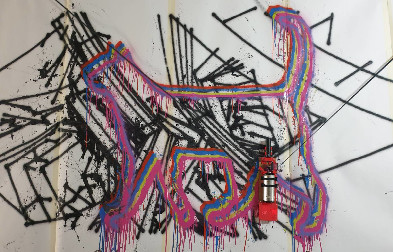
Usually, the most interesting ideas form while brainstorming over a few beers. This is also true for the dot bot project. Although the original concept used to be the construction of a robot which uses spray cans to paint murals and was supposed to be called spray bot.
This version was supposed to only be a prototype to get going with the software development. Also most of the parts were supposed to be scrapped and reused in the final version of the project.
Luckily for the bot though, we quickly fell in love with how the project turned out using permanent markers which lead to the decision to spare this bot and simply build the spray bot from ground up. Also, we decided that we are continuing the project as a two separate hardware branches running on the same software.
This project was created in collaboration with falko.berlin
First painting
This was the very first run with a picture after everything came together. Nothing was tuned in, lots of wobble and overshooting of coordinates
Second painting
With all the learnings from the first tests (and a few more unspectacular tweaking sessions), we decided to give the bot a second go on the same picture. This time with a much higher resolution and against a sturdy wall.
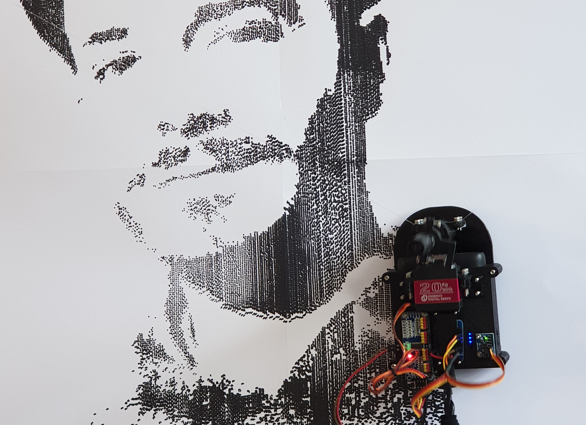
And the result is quite impressive. This picture consists of 44000 individual dots that got applied over the course of 14 h. The canvas used are 4 Din A3 pages taped together. The painted area is approximately 70 cm high and 50 cm wide.
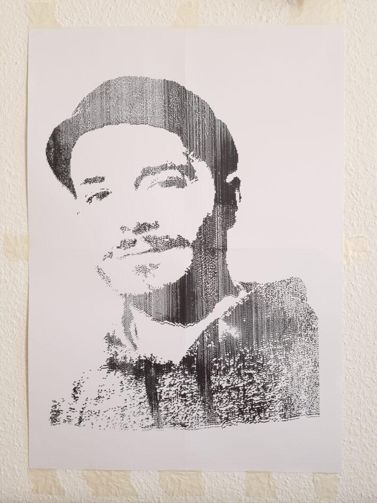
Here a few more pictures that document the states after 3 h, 6 h, 8 h and 12 h of printing


Closeup
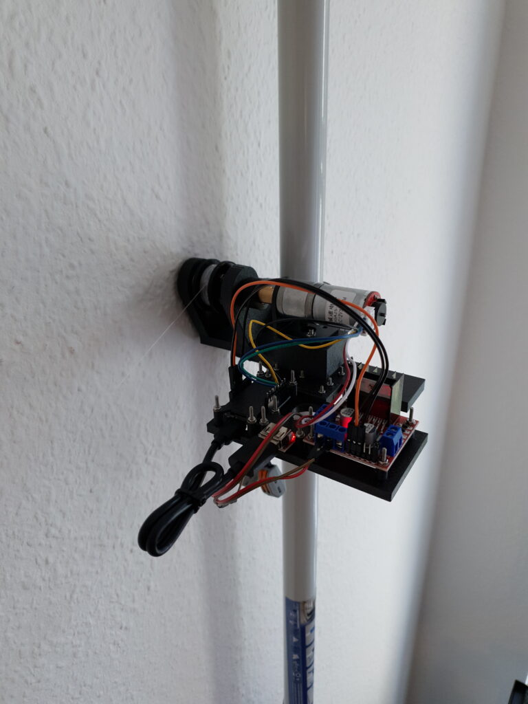
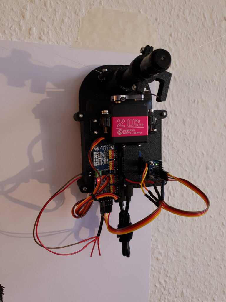
In the left picture is one of the two stations that control the position of the gondola which is shown in the right picture
How a picture becomes a dot painting:
Preparation
- Both stations need to be installed at the same height
- The distance between both stations needs to be measured and entered into the configuration mask
- The gondola needs to be positioned at the center of the drawing area
- The vertical distance from the pen to the imaginary line between both axis needs to be measured and entered as well
- The height and width of the drawable area needs to be entered
Drawing
- For each pixel, their X and Y coordinates are taken
- Some basic math is applied to scale the coordinates to the real world’s width and height values
- Then, each side is treated like a triangle, where we know the width and the height. Therefore, we are able to calculate the diagonal distance or the rope length
- Each rope length is send via a websocket to the respective station
- Both stations try to match the requested rope length as closely ass possible
- After the stations are satisfied with their position, they send an OK to the server which, after both stations replied, forwards the drawing command to the gondola
- The next pixel is chosen from the image
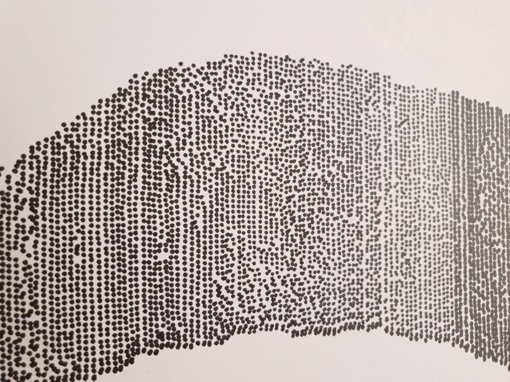
Here a close up shot of the single dots that get painted by the bot:
Technical information
On the hardware side, both stations consist each of a geared down DC motor with an encoder (with high precision at 1800 steps per rotation), an H-bridge that allows us to run the DC motor in both directions at different speeds, a 12 V to 5 V converter and an ESP8266 microcontroller. The gondola consists of a power bank, a servo motor, a servo control board, a gyroscope sensor, an ESP8266 microcontroller and a permanent marker. It hangs on two strings from the stations.
On the software side, we used a node.js webserver that communicates with a frontend which has been developed using Vue.js. The microcontrollers use websockets to communicate bidirectionally with the webserver. They e.g. send their position to the server which sends commands to motors.
On the mechanical side, all the necessary parts have been designed in Fusion360 and 3D printed on a Prusa MK3s 3D printer from PETG.
The entire system has been designed in a way that every station as well as the gondola can work self-sufficient on a single battery with no cables that need to be installed. The cables in the picture were connected to a 12 V bench power supply for easier analysis but are in fact not needed. All the data transmission is wireless using the WIFI capability of the ESP8266 ESP-12F NodeMcu Mini D1 boards. This means the system can be installed in a matter of minutes.
More examples
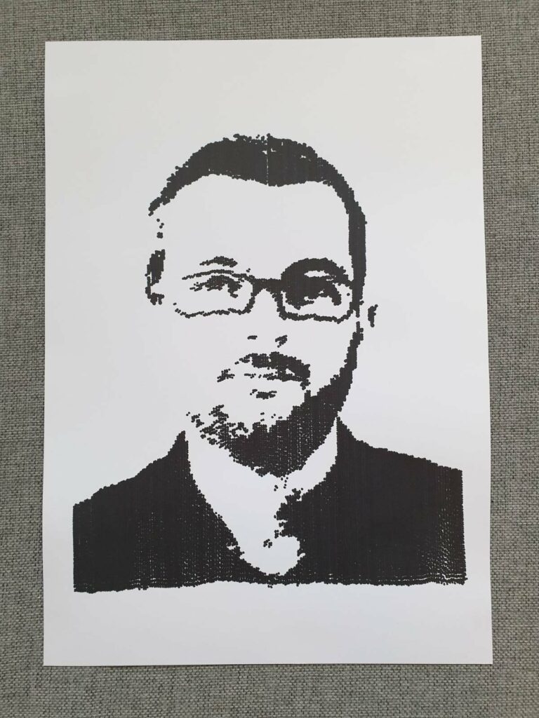
Self portrait:
This is the first painting we produced after exchanging the nylon wire for thin steel wire. Therefore we wanted to see if the accuracy holds. With only 26 cm by 30 cm, this is much smaller than we planned to go.
Left: Plotted image
Right: Source image

Accomplishments
We are honored that Autodesk, the company behind Fusion 360, asked us to use this project as a showcase for their CAD software on Instagram.
Also, we got great feedback on Reddit as well as on Twitter by many people around the world.
And finally, we got featured on the great show called HotMakes
https://www.youtube.com/watch?v=-pszrIKWrK8&t=835s
If you have an idea for an innovative and customized Arduino project that you would like to bring to life, I would be thrilled to help you with the development process. Please contact me using this email address.
